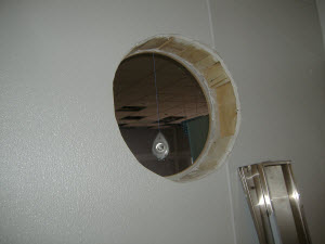
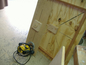
 The problem - a poorly framed hole.
Most of us have seen or used a router mounted on a pivoting board or arm to cut circles. This past spring, I was handed a difficult assignment. Someone needed to mount five 20" diameter Tiffany glass circles in the walls of a new restaurant. Someone else had framed the holes very poorly, and the owner would not let me tear out the framing to build and install window frames to properly mount the circular glass. My jig is unique because it allows you to cut rings, not just circles. Here's how I built it.
The problem - a poorly framed hole.
Most of us have seen or used a router mounted on a pivoting board or arm to cut circles. This past spring, I was handed a difficult assignment. Someone needed to mount five 20" diameter Tiffany glass circles in the walls of a new restaurant. Someone else had framed the holes very poorly, and the owner would not let me tear out the framing to build and install window frames to properly mount the circular glass. My jig is unique because it allows you to cut rings, not just circles. Here's how I built it.
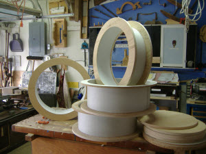 The solution - plywood rings and poly sheet sleeves. My solution was to make several rings of plywood with inner radii and rabbets to hold the glass and tubes of 1/16" poly sheets inserted through the wall to hide the ugly framing job, and an outer radius to complete the rings on both sides of the walls.

 How to make very accurate circle cuts to within 1/16"? The next problem was how to make very accurate circle cuts to within 1/16" diameters, make them for inner and outer radii, and repeat the exact process five times! Time for another jig. I made a moveable trunnion arm equipped with a plunge router.
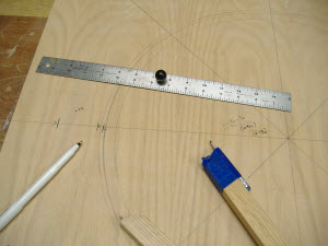
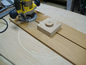
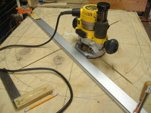 Lay out a jig and cut slots with a plunge router and the completed jig layout. The jig is a large piece of 3/4" plywood with several 1/4" slots cut to accept 1/4" carriage bolts. I laid out the pattern of the slots and the diameter of the rings and used a plunge router to cut the slots.
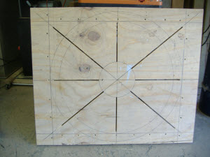 The completed layout.
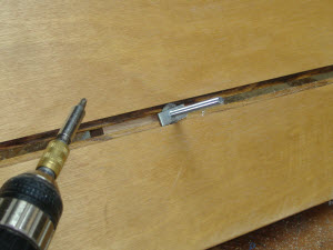
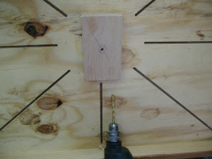 1-1/2" oak block to be used as an axle bearing and centering hole guide. Next I mounted a block of 1-1/2" thick oak, with a perfectly drilled 1/4" hole, in the center of the underside of the plywood. This block of wood was the axle bearing for the pivot of the trunnion arm. It also was used to drill the center hole through the plywood blanks after the work had been secured to the base plate of the jig.
 Then I turned my attention to the router and the trunnion arm. I wanted a stable, long trunnion arm to glide over large areas. I chose a piece of high quality 3/4" plywood, 10" wide and 34" long.
 Groove and rabbet for pivot axle/trunnion and square nut.
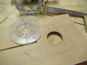
 A rectangular nut will make adjustments much easier. I turned my attention to the router and the trunnion arm. I wanted a stable and long trunnion arm to glide over large areas. I chose a piece of high quality 3/4" plywood, 10"Â wide and 34"Â long. I took the base plate off my router to use it as a template to mark the screw holes in the trunnion arm. On the underside of the trunnion arm, I cut a groove to accept the 1/4" x 6"Â long carriage bolt that I used as the pivot axle, and a 1/2" rabbet to hold a washer and rectangle nut.
View of trunnion arm and underneath of jig base. The top of the pivot axle was epoxied to a wooden knob. Another piece of 1-1/2" oak was sandwiched between the knob and the trunnion arm. This enabled the pivot axle to be moved and tightened at any desired distance from the router bit and helped ensure a very stable pivot action as the router was cutting a circle. Photo 12 shows the jig ready to use, and Photo 13 shows the router and trunnion arm next to the underneath side of the jig.
 Carriage bolt epoxied to the wooden knob, inserted through a block of oak.
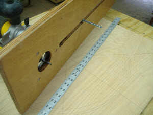 Accurate measurements and adjustments can be made and locked in place.
 Jig ready for use.
 View of trunnion arm and underneath of jig base.
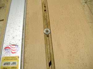
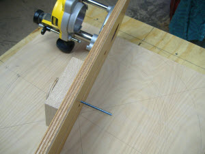
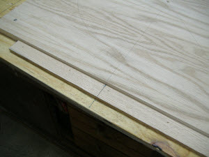
Additional layout reference stick. I added a reinforcing frame under the base that doubled as legs to provide clearance for the axle and other bolts and wing nuts. Photo 14 shows the results of the first pass of an inner radius cut. I added a reference stick on the trunnion arm to keep the upper axle block square to hold an accurate reference mark on the trunnion arm. This reference mark is located at the exact center of the pivot axle, Photo 15. From then on, repeated correct settings could be assured. Because of the number of rings needed, I added a second reference stick at the bottom of the base for a quicker setup.
 First pass of inner radius.
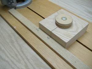 Reference stick and center of axle.
 Additional layout reference stick.
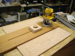
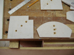 Assortment of hold down blocks.
two things make this jig unique. One is the large, stable trunnion arm and pivots axles, with repeated accurate adjustments, and two is the hold-down blocks that kept the rings centered during both inner and outer radii cuts. I made both notched blocks to hold the blanks from the outside and curved blocks to hold the rings after the inner radii were cut. 1/4" carriage bolts and wing nuts were used to hold them in a place where needed. I used 1/2" plywood to not interfere with the travel of the trunnion arm.
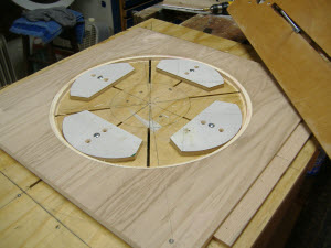 Inner hold down blocks in use kept the ring centered and in place. I must confess that because my blanks were almost as big as the jig base, I screwed them directly to the base at the corners. But, the inner curved blocks performed perfectly to hold the rings in place while cutting the outside radii.
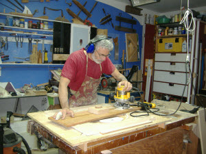 The jig in use.(No finger was cut in the making of this article.)The extra long, extra wide trunnion arm. I paid off in very stable, accurate cuts and had plenty of control over the work. Oh, the bandage in this picture - I cut my finger at work, NOT in my shop!
It was a challenging but fun jig to make. I hope this helps others.
Here are some finished product pictures: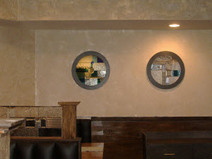
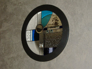
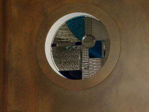
Photos By Author
Jerry Seabaugh is a registered member of the WWGOA.
Submit your favorite woodworking tip to: editor@wwgoa.com. You could earn $100 if we publish your idea.
Hi I’m new to the site and looking for a tutorial on how to cut a disk without leaving a hole in the middle of the wood? I’m need to make a round cutting board from maple and need a perfect circle. Thanks for the help
trying to access routing large circles but can't get pictures
Magnificent!!
It is a ironic that the level of artistry involved in developing this jig so far exceeds the art mounted inside!